Appearance
ACROWRX - Formation Map View
📢 - INFO
This page describes the Map View panel of the Formation page, including all map controls, trajectory options, and overlay features.
Map View
The Map View occupies the top-left area of the Formation page. It uses a Cesium-based 3D globe to display the flight trajectories of all airplanes in the formation. The map supports click-and-drag to pan, scroll-wheel to zoom, and right-click-drag to tilt and rotate.
Map Control Buttons
The map control buttons are stacked vertically in the top-right corner of the Map View:
 Trajectory Toggle
Toggles the display of the full static trajectory on the map. When enabled, each airplane displays its complete flight path as a colored polyline — not just a trailing line, but the entire trajectory from the start crop marker to the end crop marker on the timeline slider. This allows you to see the full shape of each airplane's path at a glance. The trajectory can be displayed as a flat 2D projection or as a full 3D path (see the Flat / 3D toggle below).
The visible portion of the trajectory is controlled by the crop markers on the timeline slider — see Timeline Slider & Crop Markers in the Formation Overview page.
- Tooltip (ON): "Hide Trajectory"
- Tooltip (OFF): "Show Trajectory"
 Measurement Tool
Activates an interactive measurement tool that allows you to measure distances directly on the map by clicking points.
- Tooltip (ON): "Cancel Measure"
- Tooltip (OFF): "Start Measuring"
 Follow Mode
When enabled, the map automatically centers on the selected leader airplane as it moves during playback. This is useful for keeping the active airplane in view at all times.
- Tooltip (ON): "Disable Follow"
- Tooltip (OFF): "Enable Follow (keep target centered)"
📌 - TIP
Follow mode requires a leader airplane to be selected. If no airplane is selected, the button is disabled and shows: "Select a target airplane to enable follow mode".
 Center on Judge
Re-centers the map view on the judge's location. This is a one-time action (not a toggle).
- Tooltip: "Center map on Judge location"
 Flat / 3D Trajectory Toggle
Switches between a flat (2D projected) trajectory and a full 3D trajectory that shows altitude changes.
- Tooltip (flat mode): "Enable 3D trajectory"
- Tooltip (3D mode): "Disable 3D trajectory (switch to flat)"
Basemap Selector
Opens a dropdown to change the map background imagery:
| Icon | Option | Description |
|---|---|---|
 | Satellite | High-resolution satellite imagery |
 | Streets | Street map view |
 | FAA VFR | FAA VFR Sectional charts (useful for pilots in the US) |
 | 3D Realistic | Photorealistic 3D terrain and buildings powered by Google. To enable this option, contact contact@acrowrx.com. |
Trace Size Slider
Located near the top of the map area, the Trace Size Slider controls the length of the animated trailing trace behind each airplane during playback. This is separate from the full static trajectory — it's a short trail that follows each airplane as it moves, like a smoke trace. A shorter trace shows only very recent movement, while a longer trace extends the trail further behind each airplane.
Video Sync Buttons
When a video is loaded, two additional buttons appear in the map controls:
| Icon | Button | Tooltip | Action |
|---|---|---|---|
 | Mark Sync Frame | "Mark sync frame (V key) — Set current position as video sync reference" | Sets a reference point in the data for video synchronization |
 | Apply Sync | "Sync video (Ctrl+V key) — Align marked frame with current position" | Aligns the video to match the marked data position |
📌 - TIP
You can also use the keyboard shortcuts V (mark) and Ctrl+V (apply) for faster video synchronization. Fine-tune the offset using the comma and period keys.
Map Heading Control
A circular Heading Control Ring is located in the bottom-right corner of the Map View. It allows you to rotate the map orientation by setting the heading of the aerobatic box or a runway.
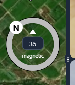
The ring has the following elements:
- Circular dial — Drag the knob around the ring to rotate the map. The N marker indicates where north sits relative to the current heading.
- Heading input — The numeric value in the center shows the current heading in degrees. You can click the input and type a precise value (0–360°).
- Magnetic / True toggle — The small text label below the input reads either "magnetic" or "true". Click it to switch between the two modes:
- Magnetic — The heading value represents magnetic heading, accounting for the magnetic declination at the flight location. This is what pilots typically use for runway headings and compass references.
- True — The heading value represents true heading (geographic north). The conversion between magnetic and true is calculated automatically based on the flight's GPS coordinates.
📌 - TIP
Most runway headings and aerobatic box orientations are given in magnetic heading. Use the magnetic mode to enter the heading directly as published. Switch to true if you are working with geographic references or map coordinates.
KML Overlays and Obstacles
KML overlays and obstacle layers are managed through their own dedicated sidebars on the left edge of the screen. See the Sidebars page for details on the  KML Overlay Sidebar and the
  Obstacles Sidebar.
Playback Controls and Leader Selection
At the bottom of the Map View, you will find the Playback Controls and the Leader Airplane Selector. The playback controls are described in the Formation Overview page. The leader airplane selector is covered in detail in the Leader & Chase Airplane Selection page.